Arduino_tutorial
Note
The following will override the ESP32 factory default code!
Tools:
PC(Win10 or uper)
Type C USB cable
Install the CH340 driver
Note
After the driver is installed, you must install the appropriate battery and turn the eCar power switch on, otherwise you will not find the COM port!

Tip
If you’ve already done this step, you can skip it!
Install the Arduino IDE
Tip
If you’ve already done this step, you can skip it!
Installing libraries
Download the library file and unzip it.
Click me to download!
Tip
The library files downloaded above are tested by us, they may not be the latest library files!
Install the library files downloaded above into the Arduino IDE.
Refer to: Link

Note
It is possible that you have already installed these libraries, but the version of the library is different, and there will be an error message during the installation process. We recommend deleting the installed libraries and using the libraries we provide!
Latest library resources(option):
ESP32-audioI2S-master: https://github.com/schreibfaul1/ESP32-audioI2S
ESP32Servo: https://madhephaestus.github.io/ESP32Servo/annotated.html
IRremote: https://github.com/Arduino-IRremote/Arduino-IRremote
Configure the Arduino IDE for ESP32
Open the arduino IDE,click “File” > “Preferences”,as shown below:

Open the button marked below:

Copy the link:
https://espressif.github.io/arduino-esp32/package_esp32_index.json
Paste it inside and click OK, as shown below:

Click “Boards Manager”:

Find the ESP32 from the pop up Boards Manager and then click install.

Tip
It is recommended to install version 2.0.14, which we are using!
Click “Tools” > “Board” > “esp32” to choose the “ESP32 Dev Module”.

ESP32 parameter Settings.

Note
All the following project code needs to be set according to the above parameters, or you will get an error!
Project
Download the example code:
Click me to download!
1_Touch
Open the “touch” example code:

Select board type:
Select COM port:

Note
The PC must have the CH340 driver installed, the eCar has the proper battery installed, and the power switch is turned on, otherwise the COM port will not be found!
ESP32 parameter Settings:
Upload the code:

Open the serial monitor and select the baud rate:

Result:

Click the touch pad of eCar, and the serial port monitor displays the data.

Code analysis:
Initialize the serial port baud rate to 115200:
Serial.begin(115200);
After printing serial port data, no line breaks:
Serial.print("T2(IO2) = ");
After printing touch data on the serial port, newline:
Serial.println(touchRead(T2));
Initialize the touch interrupt:
// For tuch T2(IO02).
touchAttachInterrupt(T2, gotTouchT2, threshold);
Define the touch interrupt mode:
// Touch ISR will be activated when touchRead is lower than the Threshold
touchInterruptSetThresholdDirection(testingLower);
Touch interrupt function:
// Interrupt function for touch T2(IO02).
void gotTouchT2(){
  if (lastTouchActive != testingLower) {
    touchActive = !touchActive;
    testingLower = !testingLower;
    // Touch ISR will be inverted: Lower <--> Higher than the Threshold after ISR event is noticed
    touchInterruptSetThresholdDirection(testingLower);
  }
}
2_Ultrasonic_module
Open the “ultrasonic_module” example code and upload it to eCar:
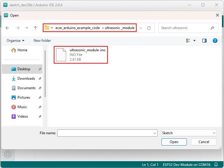
Result:
The serial port monitor prints the distance measured by the ultrasonic module.


Code analysis:
Define a thread.
//Define the first thread
xTaskCreate(
TASK_ONE,          // Task function
"TaskOne",         // Task name
32*1024,           // Stack size, set as needed
NULL,
1,                 // priority
&TASK_HandleOne    // Task handle
);
Thread function, which runs in parallel with loop():
// The function body of task1, since the input parameter is NULL,
// so the function body needs to be void * parameter, otherwise an error is reported.
void TASK_ONE(void *param ){
  for(;;){
    ...
  }
  // When the thread terminates, the thread resource is released.
  //Serial.println("Ending TaskOne!");
  //vTaskDelete( TASK_HandleOne );
}
Generate a 10 microsecond high level trigger signal to the ultrasonic module:
// trig 10us
digitalWrite(trigPin, HIGH);
delayMicroseconds(10);
digitalWrite(trigPin, LOW);
Read the high level time generated by the ECHO pin of the ultrasonic module, which is equal to the transmission time of the sound wave:
// Calculate the time of the ultrasonic echo
while(digitalRead(echoPin) == LOW){
    delayMicroseconds(10);
    if(T > 10000){ break; }  // About 100 milliseconds.
    T++;
}
T = 0;
while(digitalRead(echoPin) == HIGH){
    delayMicroseconds(10);
    if(T > 10000){ break; }  // About 100 milliseconds.
    T++;
}
Calculate the distance of the object
long dis = T * (10 + readEchoPinErr) * 0.034 / 2;
More information about ultrasonic module: Link
3_Battery_voltage
Open the “voltage” example code and upload it to eCar:
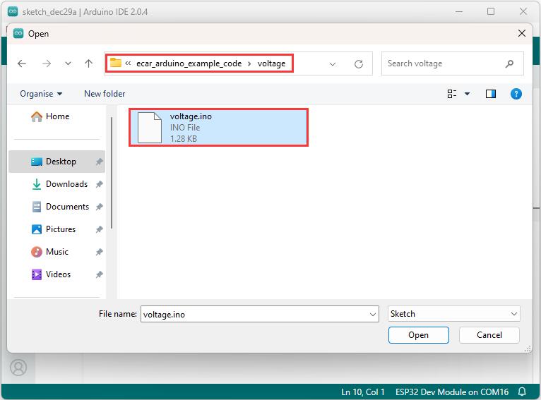
Result:
The serial port monitor prints the digital analog value and voltage value of the battery.

Code analysis:
Set the resolution of the ADC, which can be configured with 12 bit, 11 bit, 10 bit and 9 bit resolutions.
analogReadResolution(12);
Read the analog / millivolts value for pin34.
int analogValue = analogRead(34)*2;
int analogVolts = analogReadMilliVolts(34)*2;
Note: Because two 10K divider resistors are used to sample the voltage of the battery, it needs to be multiplied by two.

4_Servo
Open the “servo” example code and upload it to eCar:

Result:
Servo cycle 0–180 degrees, 180–0 degrees swing.
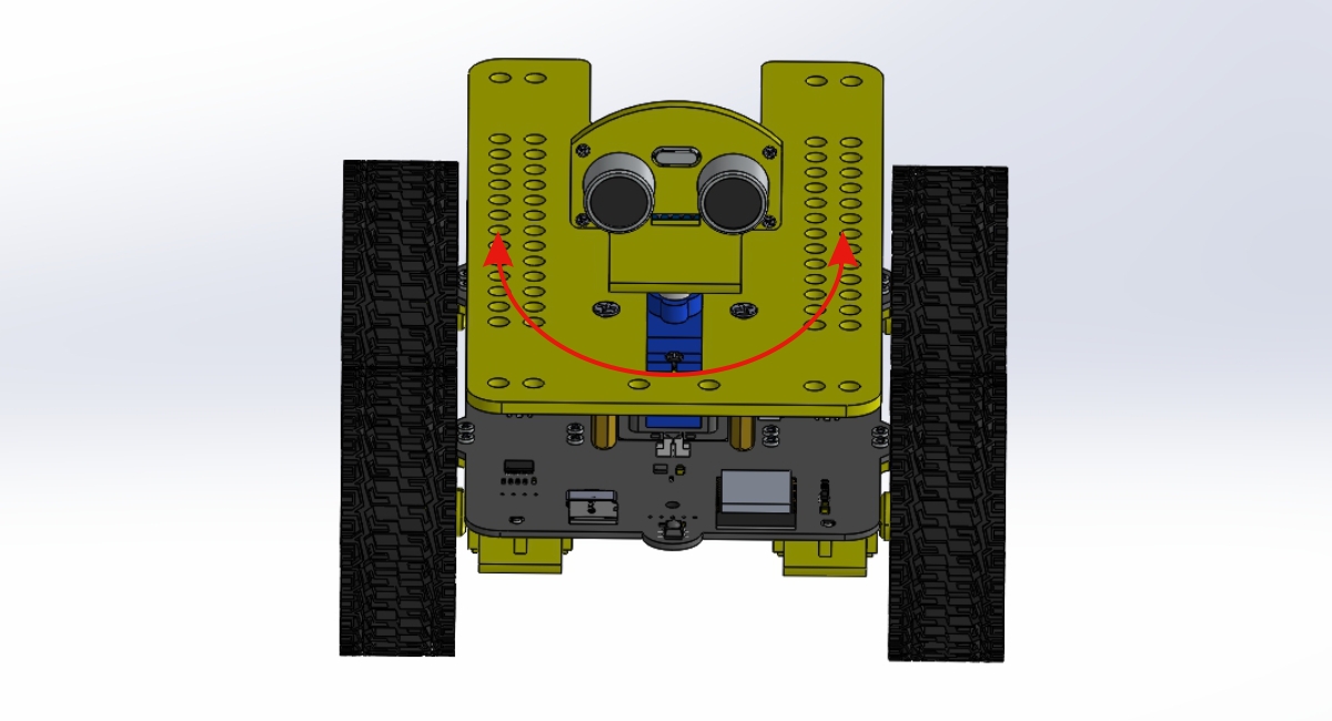
Code analysis:
Include the servo drive library into the code.
#include <ESP32Servo.h>
Initialize the two servos:
// Allow allocation of all timers
ESP32PWM::allocateTimer(0);
ESP32PWM::allocateTimer(1);
ESP32PWM::allocateTimer(2);
ESP32PWM::allocateTimer(3);
myAservo.setPeriodHertz(50);  // Standard 50hz servo
myBservo.setPeriodHertz(50);  // Standard 50hz servo

// attaches the servo on pin to the servo object
// using SG90 servo min/max of 500us and 2400us
// for MG995 large servo, use 1000us and 2000us,
// which are the defaults, so this line could be
// "myservo.attach(servoPin);"
myAservo.attach(AservoPin, 500, 2400);
myBservo.attach(BservoPin, 500, 2400);
myAservo.write(90);
myBservo.write(90);
Set the Angle of the two servos to 90 degrees:
myAservo.write(90);
myBservo.write(90);
More information about servo: Link
5_RGB_LED
A WS2812 RGB LED module is used on eCar to generate different colors of light.
Open the “RGB_LED” example code and upload it to eCar:

Result:
RGB LEDs first produce white light, and then cycle through to produce red, green, and blue light.
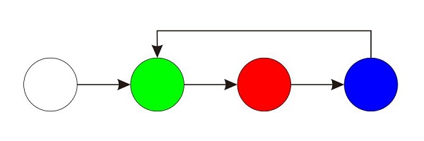
Code analysis:
An array that stores color values. The value range is: 0-255, corresponding to green, red, and blue respectively.
int color[] = {0x55, 0x11, 0x77}; // RGB value: G, R, B
The color value is converted to the WS2182 color value to be displayed and only one RGB LED is lit.
int i=0, led, col, bit;
for (led=0; led<NR_OF_LEDS; led++) {
  for (col=0; col<3; col++ ) {
    for (bit=0; bit<8; bit++){
      if ( (color[col] & (1<<(7-bit))) && (led == RGBled_index) ) {
        led_data[i].level0 = 1;
        led_data[i].duration0 = 8;
        led_data[i].level1 = 0;
        led_data[i].duration1 = 4;
      } else {
        led_data[i].level0 = 1;
        led_data[i].duration0 = 4;
        led_data[i].level1 = 0;
        led_data[i].duration1 = 8;
      }
      i++;
    }
  }
}
Send data to WS2812.
rmtWrite(rmt_send, led_data, NR_OF_ALL_BITS);
6_SD_card
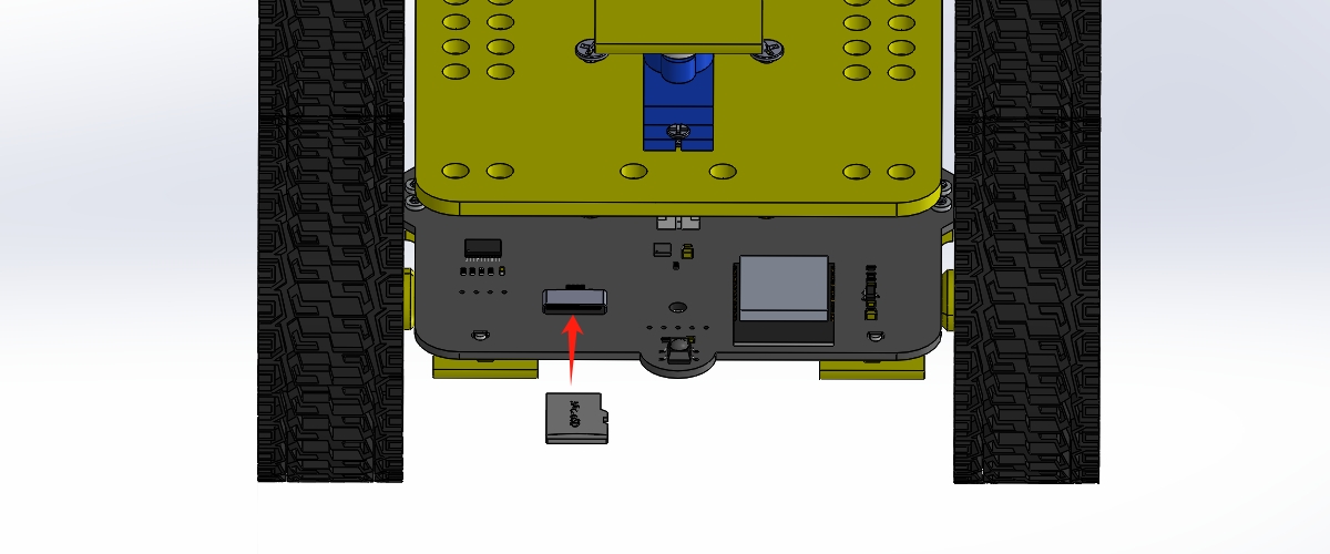
Insert the SD card into the eCar.
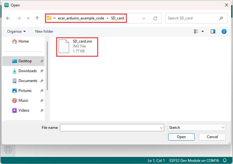
Open the “SD_card” example code and upload it to eCar:
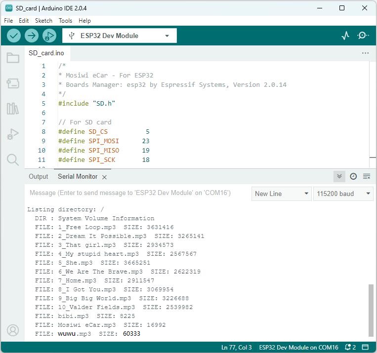
Result:
Print all the contents in the root directory of the SD card on the serial monitor.
Code analysis:
Initialize the SPI port.
pinMode(SD_CS, OUTPUT);
digitalWrite(SD_CS, HIGH);
SPI.begin(SPI_SCK, SPI_MISO, SPI_MOSI);
Initialize the SD card.
if(!SD.begin(SD_CS)){
    Serial.println("Card Mount Failed");
    return;
}
Call “listDir” function to print all the contents in the root directory of the SD card on the serial monitor.
listDir(SD, "/", 0);
More information about SPI communication protocol: Link
7_Speaker
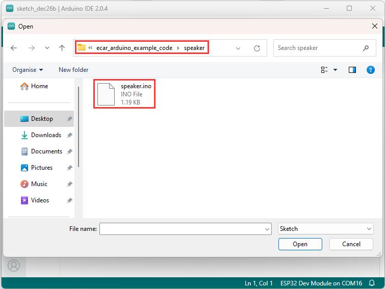
Open the “speaker” example code and upload it to eCar:
Result:
The speaker produces 440 Hz sound all the time.
Tip
Make sure the speaker is plugged into eCar!
Code analysis:
Initialize the I2S master.
if (!I2S.begin(mode, sampleRate, bps)) {
Serial.println("Failed to initialize I2S!");
while (1); // do nothing
}
Send data to the I2S slave.
I2S.write(sample);
8_MP3_player
Insert the SD card into the eCar.
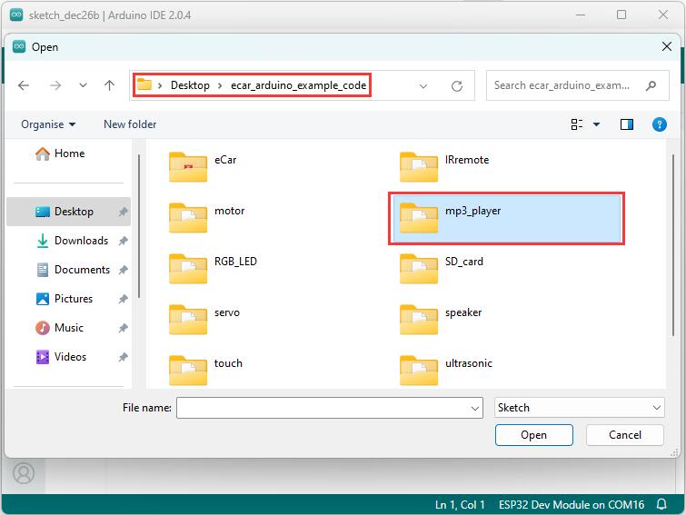
Open the “mp3_player” example code and upload it to eCar:
Result:
eCar will always loop the songs from the SD card.
Code analysis:
Define a 2-dimensional array to store the song names in the SD card.
char songs[][40]={
  "1_Free Loop.mp3",
  "2_Dream It Possible.mp3",
  "3_We Are The Brave.mp3",
  "4_My stupid heart.mp3",
  "5_She.mp3",
  "6_Big Big World.mp3",
  "7_My Love.mp3",
  "8_Hero.mp3",
  "9_Home.mp3",
  "10_I Got You.mp3",
  "11_Just One Last Dance.mp3",
  "12_Peaches.mp3",
  "13_Valder Fields.mp3",
  "14_You Raise Me Up.mp3"
};
Note
The song names in the 2-dimensional array must be the same as the song names in the SD card, otherwise the songs cannot be played!
Initialize the I2S master.
audio.setPinout(I2S_BCLK, I2S_LRC, I2S_DOUT);
Set volume.
audio.setVolume(21); // 0...21
Play the song.
audio.connecttoFS(SD, songs[songIndex]);
Read the remaining time for the currently playing song.
int t = audio.getAudioFileDuration();
Pause and play the song.
audio.pauseResume();
Stop playing the song.
udio.stopSong();
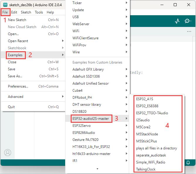
**More Code Examples: **
9_IRremote
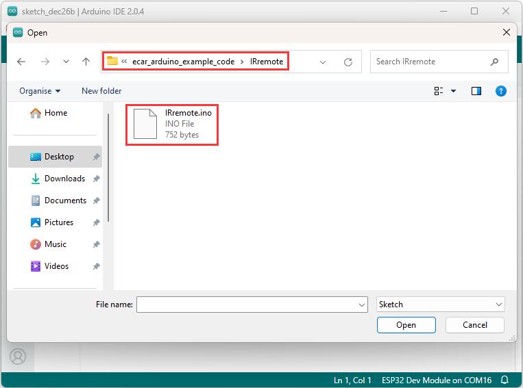
Open the “IRremote” example code and upload it to eCar:
Result:
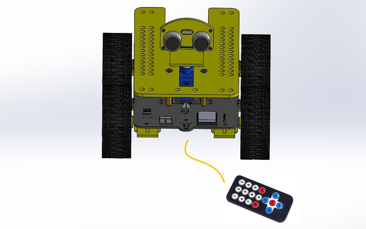
Open the serial monitor of Arduino IDE, press the button on the infrared remote control, and the serial monitor prints different values.
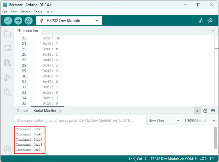
Code analysis:
Initialize the IR receiver.
IrReceiver.begin(irPin);
Determine whether infrared data is received.
if (IrReceiver.decode()){
    ...
}
The next infrared data is allowed to be received.
IrReceiver.resume();
More information about IR receiver: Link
More information about IR remote control: Link
10_Motor
Principle of motor drive:
Four motors and two leds are controlled through the I2C communication protocol.
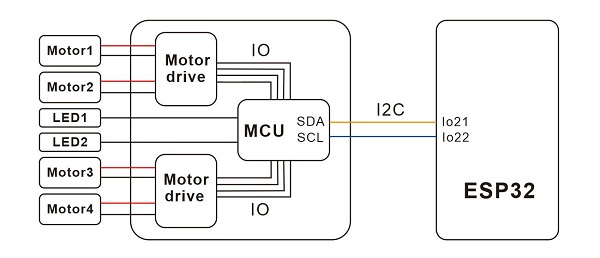
• The I2C speed is 100Khz, and the slave address is 0x2f.
• The PWM frequency between the motor and the LED is about 200Hz.
• Instruction format: 0x2f + device number + data.
Device number: 0=Motor1, 1=Motor2, 2=motor3, 3=motor4.
• data: 0-99, motors reverse speed, from small to large;
• data: 100-199, motors forward speed, from small to large (mapped to 0-99).Device number: 4=LED1, 5=LED2.
• data: 0-99, LEDs brightness, from small to large;Device number: 6=Reset.
• data=1, reset the MCU.
More information about arduino I2C: Link
More information about I2C communication protocol: Link
Example:
Open the “motor” example code and upload it to eCar:
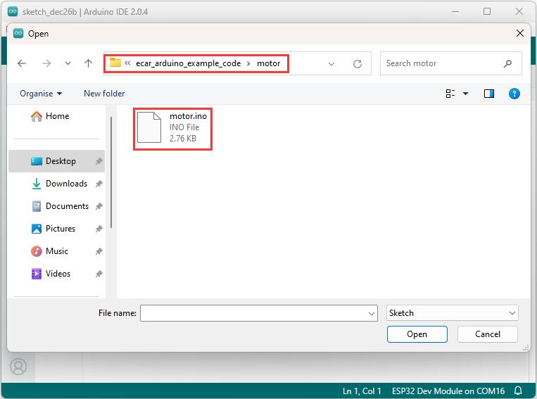
Result:
eCar keeps looping forward, stop, back, stop, turn left, stop, turn right, stop.
Code analysis:
Initialize the I2C master.
i2cMotorInit();
Select the motor and set its rotation direction and speed.
// Description: Set motor speed and steering.
// Parameters:  Motor: 0-3 --> M1-M4
//              direction: 0=CCW, 1=CW
//              speed: 0-99
void SetMotor(char motor, char direction, char speed){
  ...
}
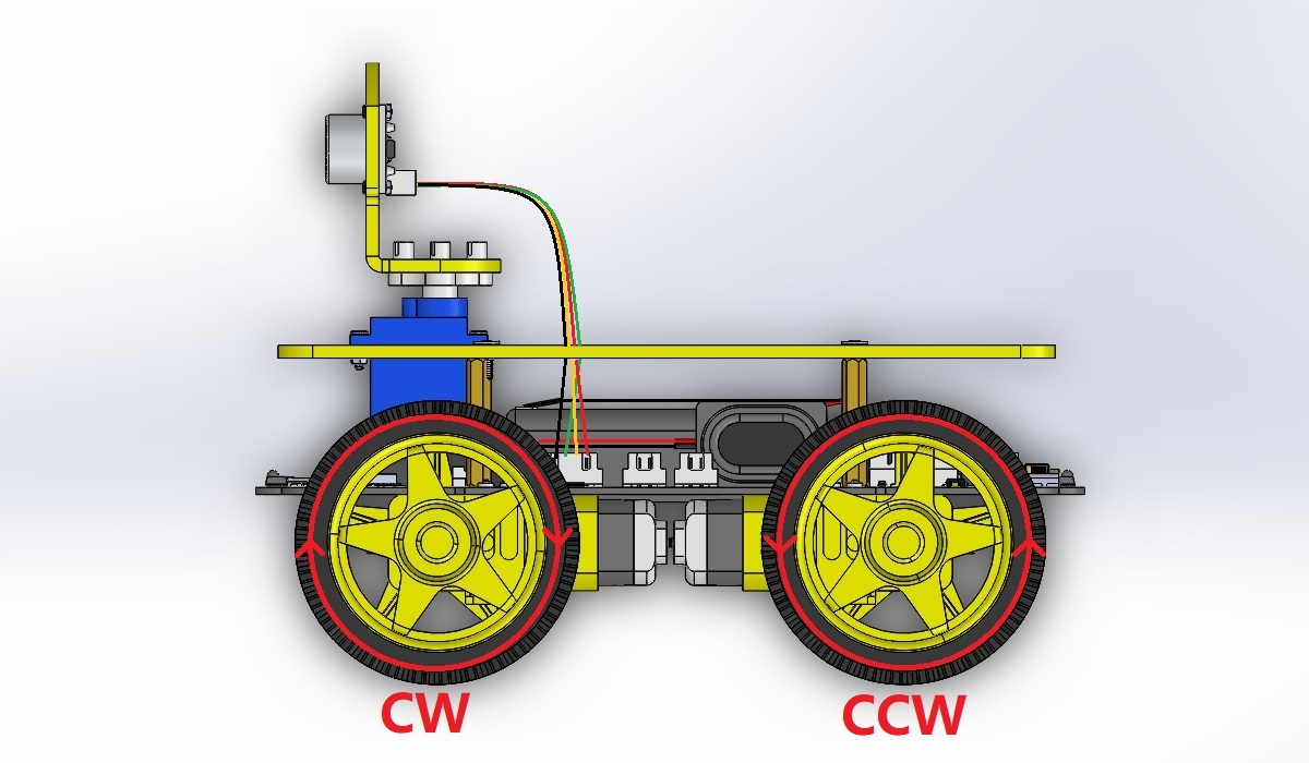
eCar runs forward.
CarRunForword(carSpeed);
eCar runs backwards.
CarRunBack(carSpeed);
eCar turns left.
CarTurnLeft(carSpeed);
eCar turns right.
CarTurnRight(carSpeed);
eCar stop.
CarStop();
Set the brightness of 2 leds, parameter value: 0-99.
LedBrightness(99);
11_WEB_app
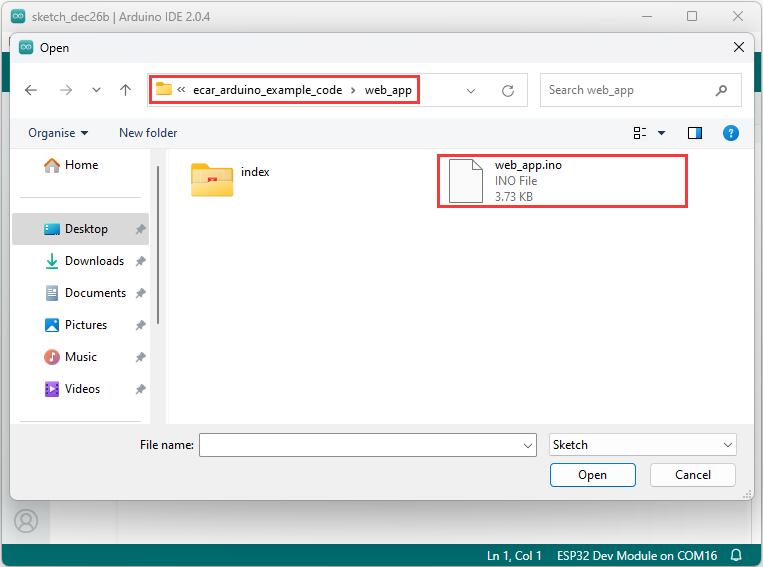
Open the “web_app” example code and upload it to eCar:
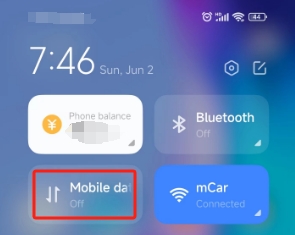
Close the mobile phone’s mobile network data, otherwise it may not enter the Web page control page!
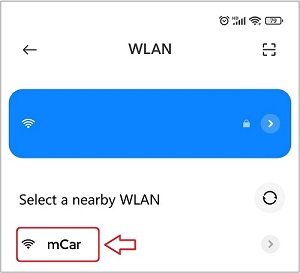
The phone or tablet searches and connects to mCar’s wifi.
Tip
After connecting to Wifi, your phone may pop up a window saying it cannot connect to the network, please ignore it!
Open your phone or tablet’s browser and link to it by typing “192.168.4.1” in the address bar.

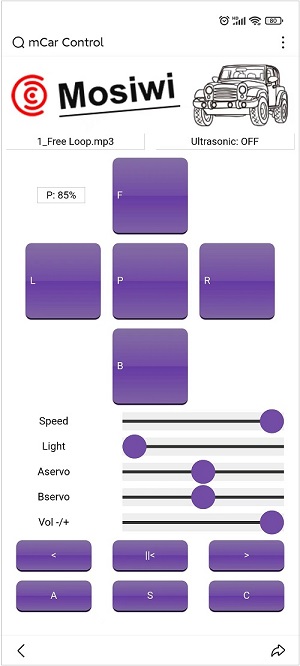
The following screen should appear in your browser.
Result:
Open the serial monitor of Arduino IDE, click or press the button on the Web App, and the serial monitor prints different values.
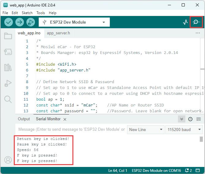
Button |
Serial port monitor display |
|---|---|
Left display window |
Left display window |
Right display window |
right display window |
P: xxx% |
P: 100% |
F |
F key is pressed! |
B |
B key is pressed! |
L |
L key is pressed! |
R |
R key is pressed! |
P |
P key is pressed! |
Speed |
Speed: xxx |
Light |
Light: xxx |
Aservo |
Aservo: xxx |
Bservo |
Bservo: xxx |
Volt +/- |
Volume: xx |
< |
Return key is clicked! |
||< |
Pause key is clicked! |
> |
Next key is clicked! |
A |
A key is clicked! |
S |
S key is clicked! |
C |
C key is clicked! |
Code analysis:
Set the working mode of ESP32, 1 is AP mode and 0 is Station mode.
bool ap = 1;
In AP (Access Point) mode, it sets its own Wifi name. In Station mode, set the name of the WiFi to connect to.
const char* ssid = "mCar";
In AP (Access Point) mode, it sets its own Wifi password. In Station mode, set the WiFi password to connect to. If password is empty, no password is required.
const char* password = "";
Enable http server function of ESP32 module.
startCarServer();
Let the three display windows of WEB_App display different strings.
displayWindow(0, "Left display window");
displayWindow(1, "right display window");
displayWindow(2, "P: 100%");
12_eCar
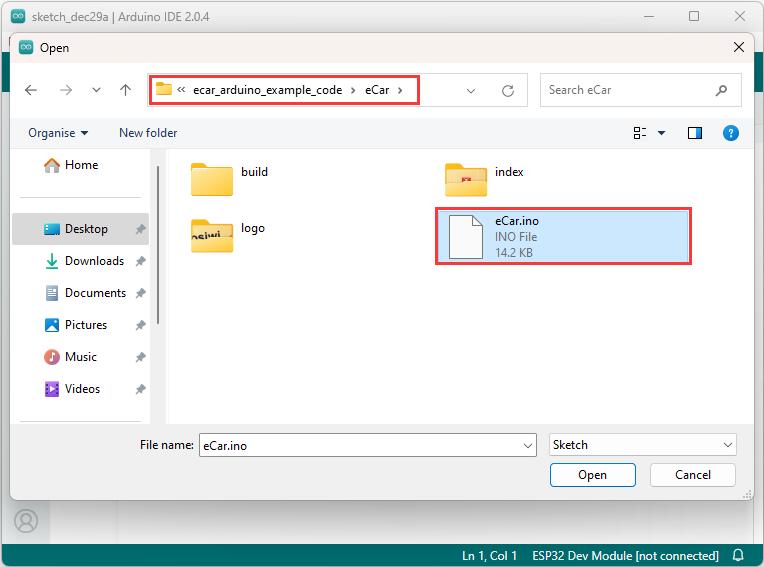
Open the “eCar” example code and upload it to eCar:
Result:
The function of this code is the same as the function of eCar out of the factory, which is also the integration of the above project function, so no more parsing code!
Control method: Link
Other Resources (option)
Arduino Getting Started Learning Kit
End!