Pi4_tutorial
This tutorial is based on C1K0001 4in1 basic learning kit and C language, if you do not have knowledge of the C language, it is recommended to learn the Arduino tutorial first.
Prepared knowledge (Important)
1. Learn about Basic learning shield.
2. Learn about 3in1 basic learning shield.
3. Raspberry pi4 basics
4. Install the GPIO library for Raspberry pi4
5. Download example code
Use the Raspberry PI terminal to download the example code:
git clone https://github.com/Mosiwi/Mosiwi-basic-learning-kit

The file in the “Mosiwi-basic-learning-kit-for-arduino -> pi4 -> c” folder is the example code:
cd ~/Mosiwi-basic-learning-kit/pi4/c

ls

Document architecture:

If you are a newbie, the files in the “src” folder are not recommended to modify them, which may cause the code in the “examples” folder to compile incorrectly.
Each example folder contains a “Makefile”, “xxx.o”, and “xxx.c” files, as well as an execution file.
The “xxx.o” and execution files are generated from the “Makefile” file.
If you are a newbie, it is not recommended to modify the contents of the “Makefile” and the name of the “xxx.c” file, which may cause compilation errors.
If the content of the xxx.c file is modified, you need to compile it again to generate an executable file.
sudo make
Run the execution file with the following command:
sudo ./xxx
Resource: GNU Make(Makefile)
Basic Example (Important): Terminal
Objective:
Run the example code.
Recompile the example code.
Modify and recompile the example code.
Objective_1:
Terminal into the “1.0.0_Terminal” folder:
cd ~/Mosiwi-basic-learning-kit/pi4/c/examples/1.0.0_Terminal/
Permission to view execution files:
ls -al

r: Read permission. w: Write permission. x: Execute permission.
If the file does not have execution permissions as shown in the figure above, you need to add execution permissions:
chmod 777 terminal
ls -al

Run the compiled example code:
sudo ./terminal

Objective_2:
Delete the latest executable file and then view the files in the folder:
rm terminal
ls

The “terminal” executable is no longer visible from the image above, now re-run the “Makefile” file to generate the executable “terminal” file.
sudo make
ls

Objective_3:
Edit the example code using the nano tool that comes with the Raspberry PI system:
sudo nano terminal.c

When the editing is complete, save the file by typing the following command on the keyboard and exit the nano editor:
Ctrl+O           // save file
Ctrl+C           // closed file
Recompile the “terminal.c” source file:
sudo make
ls
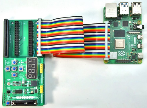
Wiring diagram
Turn off the Raspberry PI and connect the Raspberry PI to the expansion board with a 40P color cable:
Then restart Raspberry PI and TUTTY.
Example1: Arithmetic operator
Run the following command on the terminal:
cd ~/Mosiwi-basic-learning-kit/pi4/c/examples/1.0.1_Arithmetic_operation/
chmod 777 arithmetic_operation
sudo ./arithmetic_operation

Example2 Blink
Pins to be used:
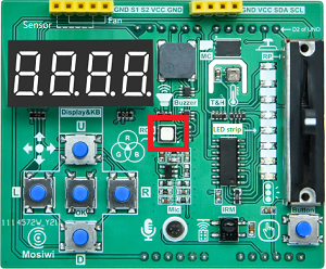
Red RGB LED: 23(Wiringpi) or 13(BCM)
Schematic diagram:

Demonstration:
Run the following command on the terminal:
cd ~/Mosiwi-basic-learning-kit/pi4/c/examples/1.1.0_Blink/
chmod 777 blink
sudo ./blink
The red LED lights on the expansion board are lit at one-second intervals.
Example3 Button
Pins to be used:
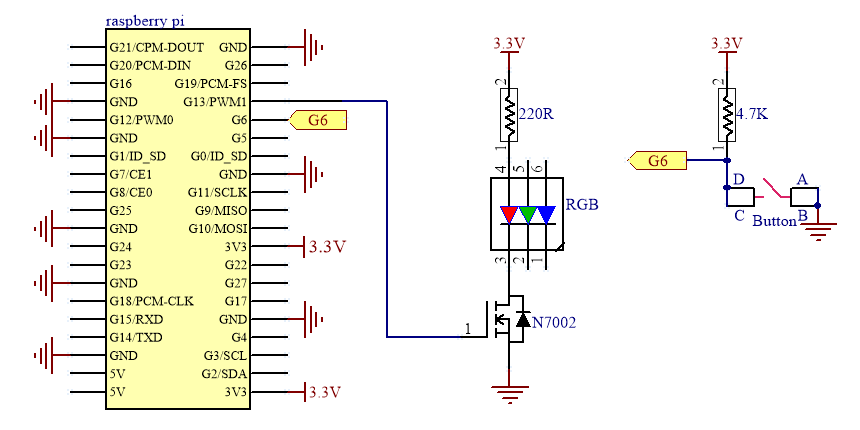
Red RGB LED: 23(Wiringpi) or 13(BCM)
Button: 22(Wiringpi) or 6(BCM)
Schematic diagram:
Demonstration:
Run the following command on the terminal:
cd ~/Mosiwi-basic-learning-kit/pi4/c/examples/1.2.0_Button/
chmod 777 button
sudo ./button
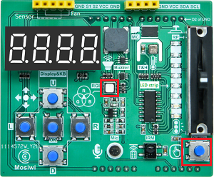
After uploads the code, the green RGB led on the expansion board is always off, and if the “Button” on the extension board is pressed, the LED is turned on.
Example4 Buzzer
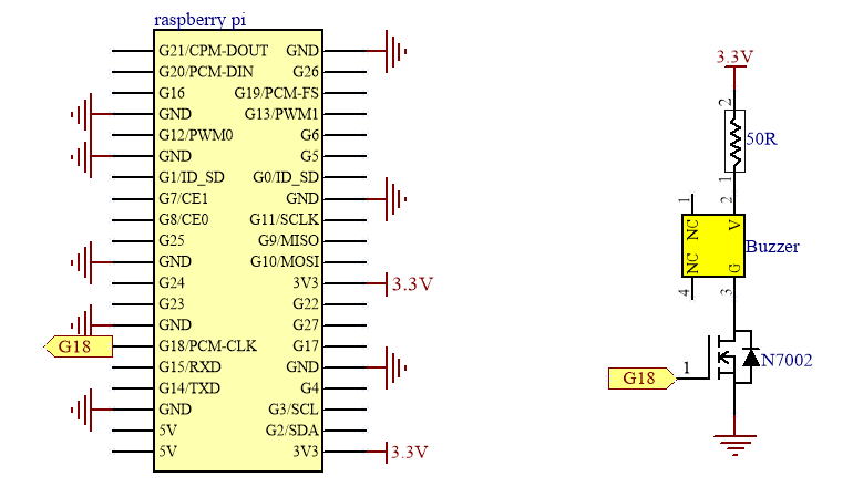
Pins to be used:
Buzzer: 1(Wiringpi) or 18(BCM)
Schematic diagram:
Demonstration:
Run the following command on the terminal:
cd ~/Mosiwi-basic-learning-kit/pi4/c/examples/2.2.0_Buzzer/
chmod 777 buzzer
sudo ./buzzer
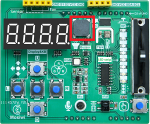
After uploading the code, the buzzer on the expansion board will keep beeping with a fixed frequency and different volumes.
Example5 RGB LED
Pins to be used:
Red RGB LED: 23(Wiringpi) or 13(BCM)
Green RGB LED: 24(Wiringpi) or 19(BCM)
Blue RGB LED: 26(Wiringpi) or 12(BCM)
Schematic diagram:

Demonstration:
Run the following command on the terminal:
cd ~/Mosiwi-basic-learning-kit/pi4/c/examples/2.2.0_Buzzer/
chmod 777 buzzer
sudo ./buzzer
After uploading the code, the buzzer on the expansion board will keep beeping with a fixed frequency and different volumes.
Example6 Fan
Pins to be used:
S1(INB): 23(Wiringpi) or 13(BCM)
S2(INA): 24(Wiringpi) or 19(BCM)
Schematic diagram:

Wiring diagram:

Demonstration:
Run the following command on the terminal:
cd ~/Mosiwi-basic-learning-kit/pi4/c/examples/2.8.0_Fan_PWM/
chmod 777 fan_pwm
sudo ./fan_pwm
The fan rotates clockwise and counterclockwise, and the speed changes from small to large, and then from large to small.

More info: Fan module
Example7 Potentiometer
Pins to be used:
SDA: 8(Wiringpi) or 2(BCM)
SCL: 9(Wiringpi) or 3(BCM)
Schematic diagram:
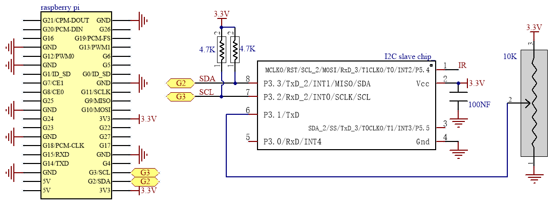
Note: The I2C slave chip is integrated on the 3in1 Basic learning shield board to process the data of the potentiometer.
Demonstration:
Run the following command on the terminal:
cd ~/Mosiwi-basic-learning-kit/pi4/c/examples/1.3.0_Analog_sr/
chmod 777 analog_sr
sudo ./analog_sr
Push the potentiometer up and down, and the terminal prints the corresponding analog value and voltage value.

Note
Raspberry Pi4 reads the analog value of the potentiometer through the I2C expansion chip on the “3in1_basic_learning_shield”.
Example8 Microphone
Pins to be used:
SDA: 8(Wiringpi) or 2(BCM)
SCL: 9(Wiringpi) or 3(BCM)
Schematic diagram:

Note: The I2C slave chip is integrated on the 3in1 Basic learning shield board to process the data of the microphone.
Demonstration:
Run the following command on the terminal:
cd ~/Mosiwi-basic-learning-kit/pi4/c/examples/2.3.0_Microphone/
chmod 777 microphone
sudo ./microphone
After running the code, the terminal prints the analog value of the amplified sound and the voltage value.

Note
Raspberry Pi4 reads the analog value of the microphone through the I2C expansion chip on the “3in1_basic_learning_shield”.
Example9 Ultrasonic
Pins to be used:
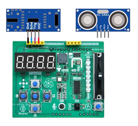
S1(echo of ultrasonic): 23(Wiringpi) or 13(BCM)
S2(trig of ultrasonic): 24(Wiringpi) or 19(BCM)
Schematic diagram:

Wiring diagram:
Demonstration:
Run the following command on the terminal:
cd ~/Mosiwi-basic-learning-kit/pi4/c/examples/2.7.0_Ultrasonic/
chmod 777 ultrasonic
sudo ./ultrasonic
After the code is uploaded, the obstacle is placed in front of the ultrasonic sensor, and the distance measured by the ultrasonic sensor is printed at the terminal.

More info: Ultrasonic sensor
Example10 Led-strip
Pins to be used:
Led-strip
DS: 0(Wiringpi) or 17(BCM)
SH_CP: 2(Wiringpi) or 27(BCM)
ST_CP: 3(Wiringpi) or 22(BCM)
Microphone
SDA: 8(Wiringpi) or 2(BCM)
SCL: 9(Wiringpi) or 3(BCM)
Wiring diagram:
Led-strip

Microphone
Note: The I2C slave chip is integrated on the 3in1 Basic learning shield board to process the data of the microphone.
Demonstration:
Run the following command on the terminal:
cd ~/Mosiwi-basic-learning-kit/pi4/c/examples/2.1.2_Led_strip/
chmod 777 led_strip
sudo ./led_strip
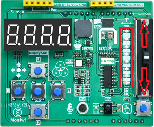
The more you push the slide resistor up, the more LEDs are turned on; the more you push the slide resistor down, the more LEDs are turned off.
Example11 Thread
Pins to be used:
Red RGB LED: 23(Wiringpi) or 13(BCM)
Demonstration:
Run the following command on the terminal:
cd ~/Mosiwi-basic-learning-kit/pi4/c/examples/1.6.0_Thread/
chmod 777 thread
sudo ./thread
The red LED lights on the expansion board are lit at one-second intervals.
Example12 Digital_tube_Keyboard
Pins to be used:
MISO: 13(Wiringpi) or 9(BCM)
MOSI: 12(Wiringpi) or 10(BCM)
CLK: 14(Wiringpi) or 11(BCM)
KEY-INT: 21(Wiringpi) or 5(BCM)
Wiring diagram:

Demonstration:
Run the following command on the terminal:
cd ~/Mosiwi-basic-learning-kit/pi4/c/examples/1.8.0_Digital_tube_Button_spi/
chmod 777 digital_tube_button_spi
sudo ./ldigital_tube_button_spi
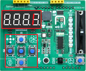
The 4-bit digital display tube displays “16.0” when the “U” key is pressed; “8.0” is displayed when the “D” key is pressed; “4.0” is displayed when the “L” key is pressed; “2.0” is displayed when the “R” key is pressed. Displays “1.0” when the “OK” key is pressed.
U |
D |
L |
R |
OK |
|---|---|---|---|---|
16 |
8 |
4 |
2 |
1 |
Note
The 4-bit 8-segment digital tube and 5 keys on the “Basic learning shield” occupy pins 5(key trigger signal output), 10(MOSI), 9(MISO) and 11(CLK) of the Pi4, and the CS control pin is not required.
Example13 Ir-receiver
Pins to be used:
SDA: 8(Wiringpi) or 2(BCM)
SCL: 9(Wiringpi) or 3(BCM)
Schematic diagram:
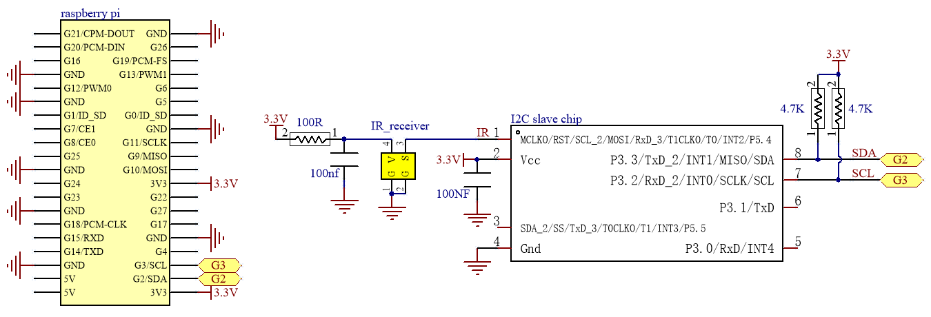
Note: The I2C slave chip is integrated on the 3in1 Basic learning shield board to process the data of the infrared receiving sensor.
Demonstration:
Run the following command on the terminal:
cd ~/Mosiwi-basic-learning-kit/pi4/c/examples/2.6.0_IRrecvDemo/
chmod 777 ir_recvDemo
sudo ./ir_recvDemo
When the infrared remote controller presses the button, point to the infrared receiver on the expansion board, and the terminal will print the button value.
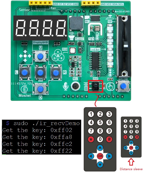
Pi4 will get 2 bytes of data, the first byte is the inverse code of the address of the infrared remote control device, and the second byte is the command code of the infrared remote control device.

data: 65432 = 0xff98

Device inverse code:
0xff = 0b11111111 = 255

Device code:
0x00 = 0b00000000 = 0
Note
Raspberry Pi4 reads the value of the Ir-receiver through the I2C expansion chip on the “3in1_basic_learning_shield”.
Example14 Thermohygrometer
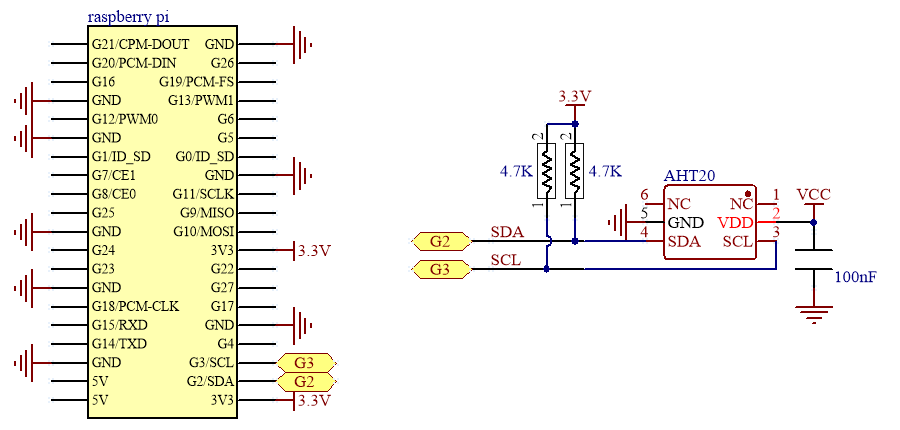
Pins to be used:
AHT20
SDA: 8(Wiringpi) or 2(BCM)
SCL: 9(Wiringpi) or 3(BCM)
Display
MISO: 13(Wiringpi) or 9(BCM)
MOSI: 12(Wiringpi) or 10(BCM)
CLK: 14(Wiringpi) or 11(BCM)
KEY-INT: 21(Wiringpi) or 5(BCM)
Schematic diagram:
AHT20
Display
Demonstration:
Run the following command on the terminal:
cd ~/Mosiwi-basic-learning-kit/pi4/c/examples/2.5.0_Thermohygrometer/
chmod 777 thermohygrometer
sudo ./thermohygrometer
The 4-digit digital tube displays the temperature and humidity in a cycle with a period of 10 seconds.

Example15 EEPROM
Pins to be used:
EEPROM: 27(Wiringpi) or 16(BCM)
Schematic diagram:

Demonstration:
Run the following command on the terminal:
cd ~/Mosiwi-basic-learning-kit/pi4/c/examples/2.4.0_EEPROM_ReadWriteSkip/
chmod 777 eeprom_ReadWriteSkip
sudo ./eeprom_ReadWriteSkip
Read 128 bytes of EEPROM data.
Write 8 bytes of data to EEPROM.
Read 128 bytes of EEPROM data.
The 8-byte data written to EEPROM is read back and converted to the character: <Mosiwi>

Example16 Smart fan
Demonstration:
Run the following command on the terminal:
cd ~/Mosiwi-basic-learning-kit/pi4/c/examples/2.8.2_Intelligent_fan/
chmod 777 intelligent_fan
sudo ./intelligent_fan
This is an intelligent fan with temperature control mode and remote control mode.
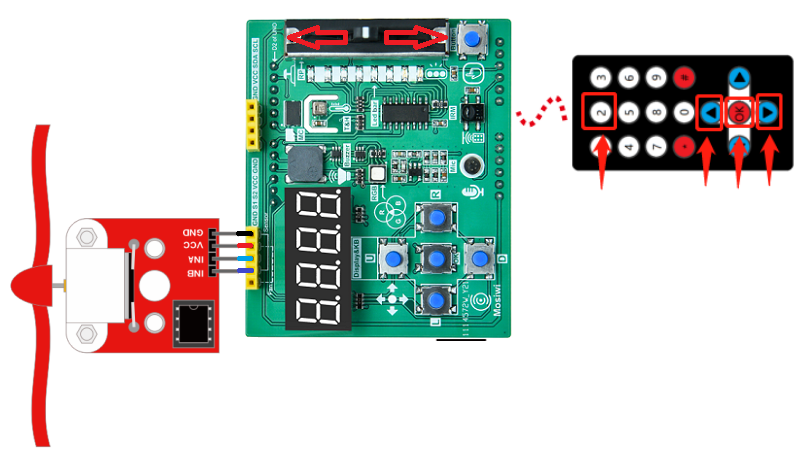
Function of infrared remote control button:
2: Turn on and off temperature control mode
▲: Fan speed plus
▼: Fan speed minus
OK: Turn on and off fan
RGB LED function Tips:
If the light is red, the fan is turned on; otherwise, the fan is turned off.
If the light is green, the fan is turned on; otherwise, the fan is turned off.
Special Notes:
When the temperature mode is opened, the fan will start automatically when the temperature is higher than 35 degrees; It will automatically turn off when it is below 16 degrees. If the temperature returns to 16-35 degrees, you can turn on or off the fan through the remote control.
The fan speed can be controlled by remote control in both temperature control mode and remote control mode.
End!