Arduino_zero-based_tutorial
This tutorial only focuses on practical operation, without the need to understand the principles, and understands the simplest Arduino programming operation, so that learners can get a sense of achievement and arouse their interest.
Previous preparation
Install the Arduino IDE.
Install the Mosiwi basic learning kit library.
Basic operation of the Arduino UNO R3.
Tip
If you’ve already done some of the steps above, you don’t need to go through the steps you’ve already done.
Chapter1 RGB LED
Connect control board to your computer with USB cable:

Open “2.0.0 RGB led” Example:

Select motherboard with COM port:

Upload code:

Experimental result:
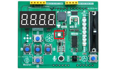
RGB LED lights flash red, green, blue, yellow, cyan, mauve and white.
Chapter2 waterfall light
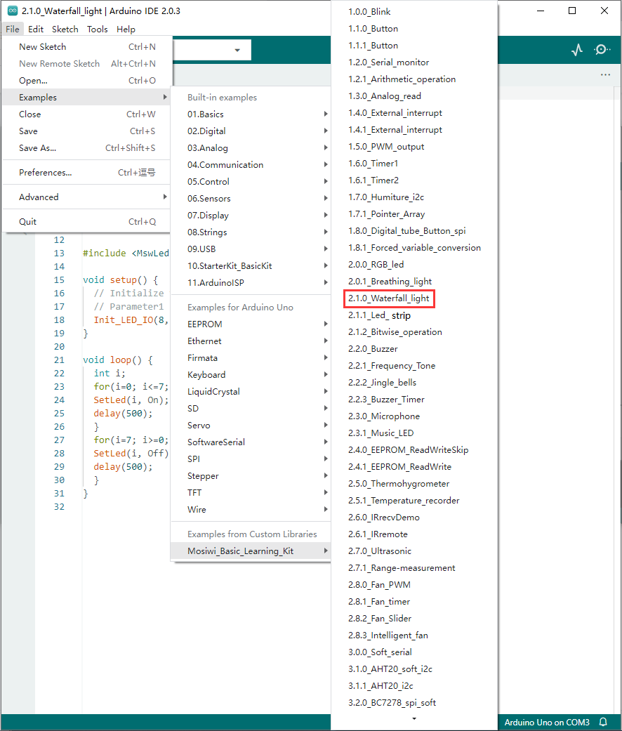
Open “2.1.0_Waterfall_light” Example:
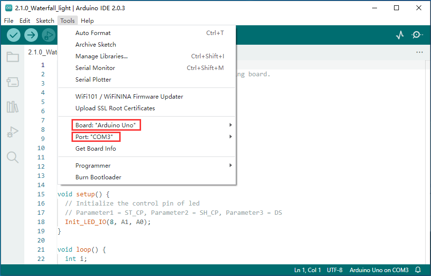
Select motherboard with COM port:
Upload code:

Experimental result:
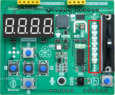
Eight white LED lights turn on and off in a cycle.
Chapter3 Led bar
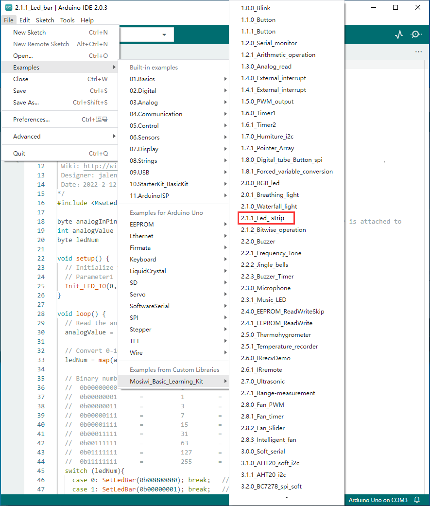
Open “2.1.1_Led_strip” Example:
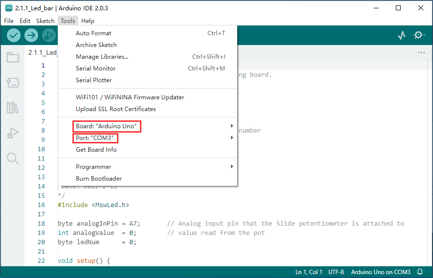
Select motherboard with COM port:
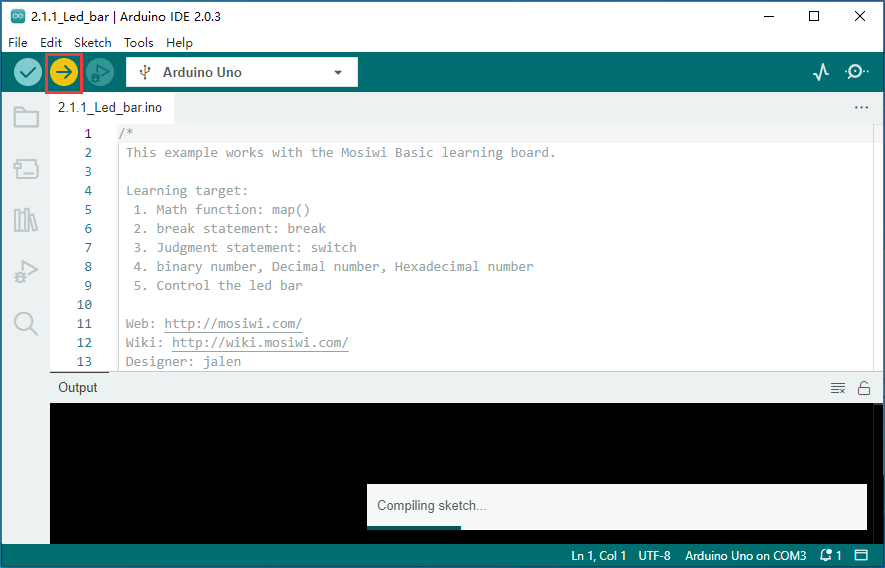
Upload code:
Experimental result:
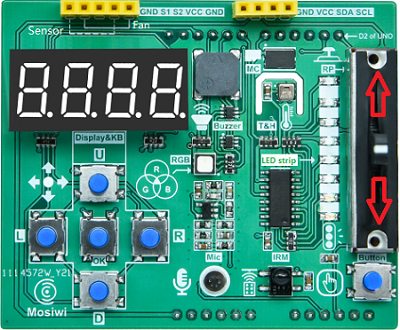
Push up the potentiometer to light more white LED lights, push down the potentiometer to extinguish more white LED lights.
Chapter4 music LED
Open “2.3.1_Music_LED” Example:
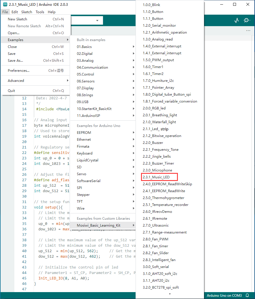
Select motherboard with COM port:

Upload code:
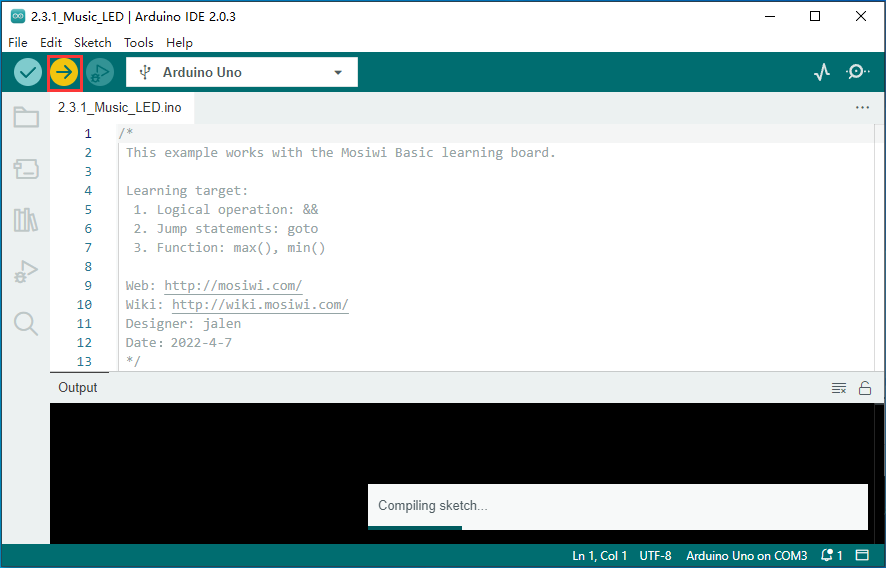
Experimental result:

When you sing into a microphone or play music on your device, LED lights pulsate to the rhythm of the song.
Chapter5 IR remote
Open “2.6.1_IRremote” Example:
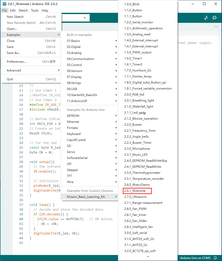
Select motherboard with COM port:

Upload code:

Experimental result:
Use the infrared remote control to repeatedly press the “OK” key in front of the infrared receiver on the expansion board to turn on and off the red LED light on the expansion board.

Note
Button batteries must be installed when using the infrared remote control. If the infrared remote control has been allocated with button batteries, the separator at the bottom of the remote control must be pulled out.
Chapter6 button
Open “1.1.0_Button” Example:
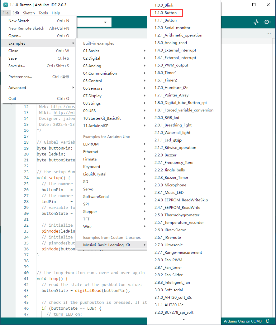
Select motherboard with COM port:
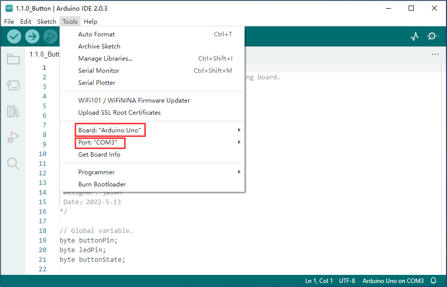
Upload code:
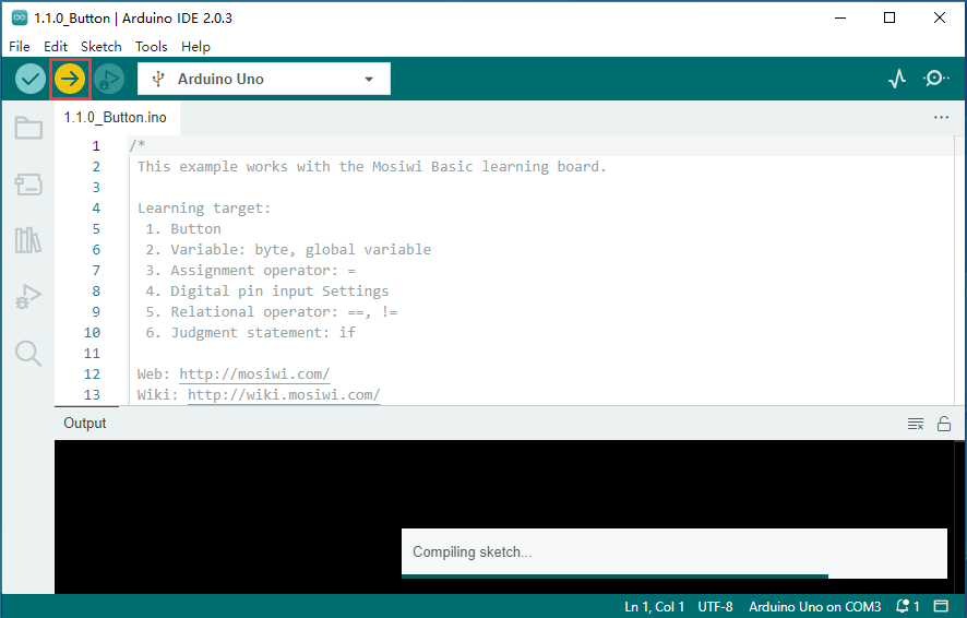
Experimental result:
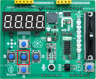
Press and hold the OK button on the expansion pad to light up the red LED light. Release your hand and turn off the red LED light.
Chapter7 digital tube and button (spi)
Open “1.8.0_Digital_tube_Button_spi” Example:
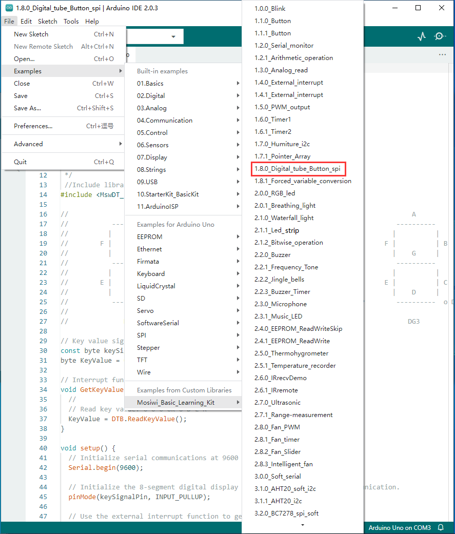
Select motherboard with COM port:

Upload code:
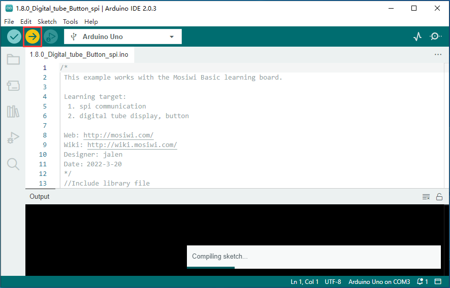
Experimental result:
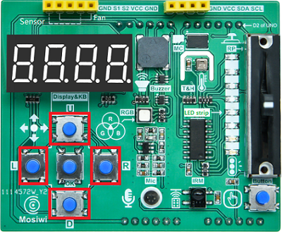
When pressing the ”U” key, the 4-digit digital tube displays “16.0”;
When pressing the ”D” key, the 4-digit digital tube displays “8.0”;
When pressing the ”L” key, the 4-digit digital tube displays “4.0”;
When pressing the ”R” key, the 4-digit digital tube displays “2.0”;
When pressing the ”OK” key, the 4-digit digital tube displays “1.0”.
Chapter8 thermohygrometer
Open “2.5.0_Thermohygrometer” Example:

Select motherboard with COM port:
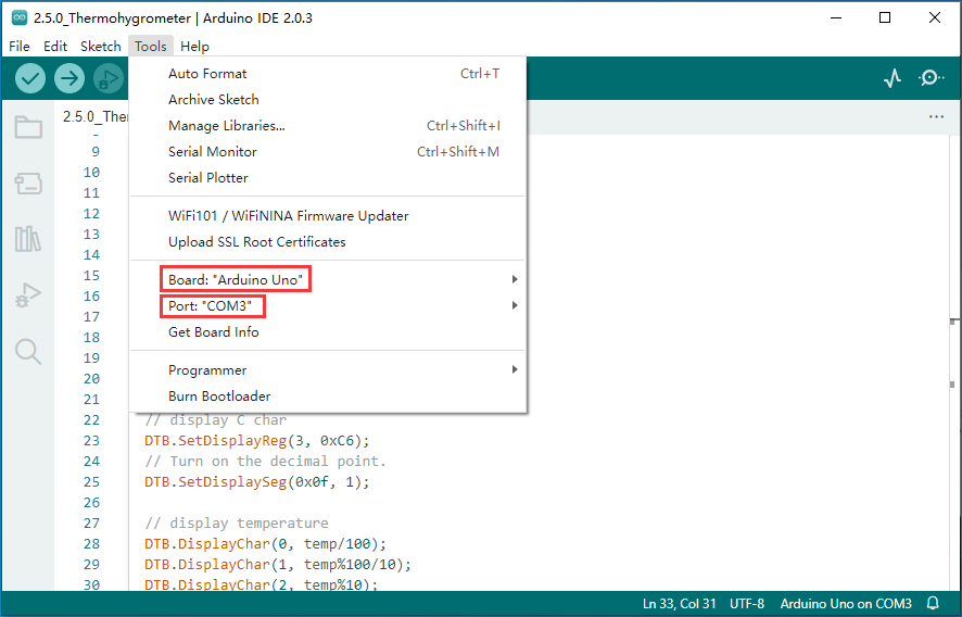
Upload code:

Experimental result:
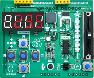
The 4-digit digital tube will display the current ambient temperature and humidity in degrees Celsius.
Chapter9 thermohygrometer
Open “2.4.2_Thermohygrometer” Example:

Select motherboard with COM port:

Upload code:

Experimental result:
The current ambient temperature is displayed on a 4-digit digital tube in 3 seconds. The format is xx.xC “z. Temperature data is stored every 0.5 minutes in the eeprom of the expansion board, which is a kind of memory that does not lose power data.
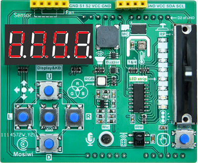
Open the serial port monitor as shown in the following figure, press the ”OK” button on the expansion board, and the serial port monitor will print out the temperature data in the eeprom.

If you are using an IDE above 2.0, you can also display the data as a temperature graph as follows:

Note
After following steps 1 and 2, click the “OK” key on the expansion board, multiple curves will be displayed. Then, select “value 1” according to step 3.
Chapter10 jingle bells
Open “2.2.2_Jingle_bells” Example:
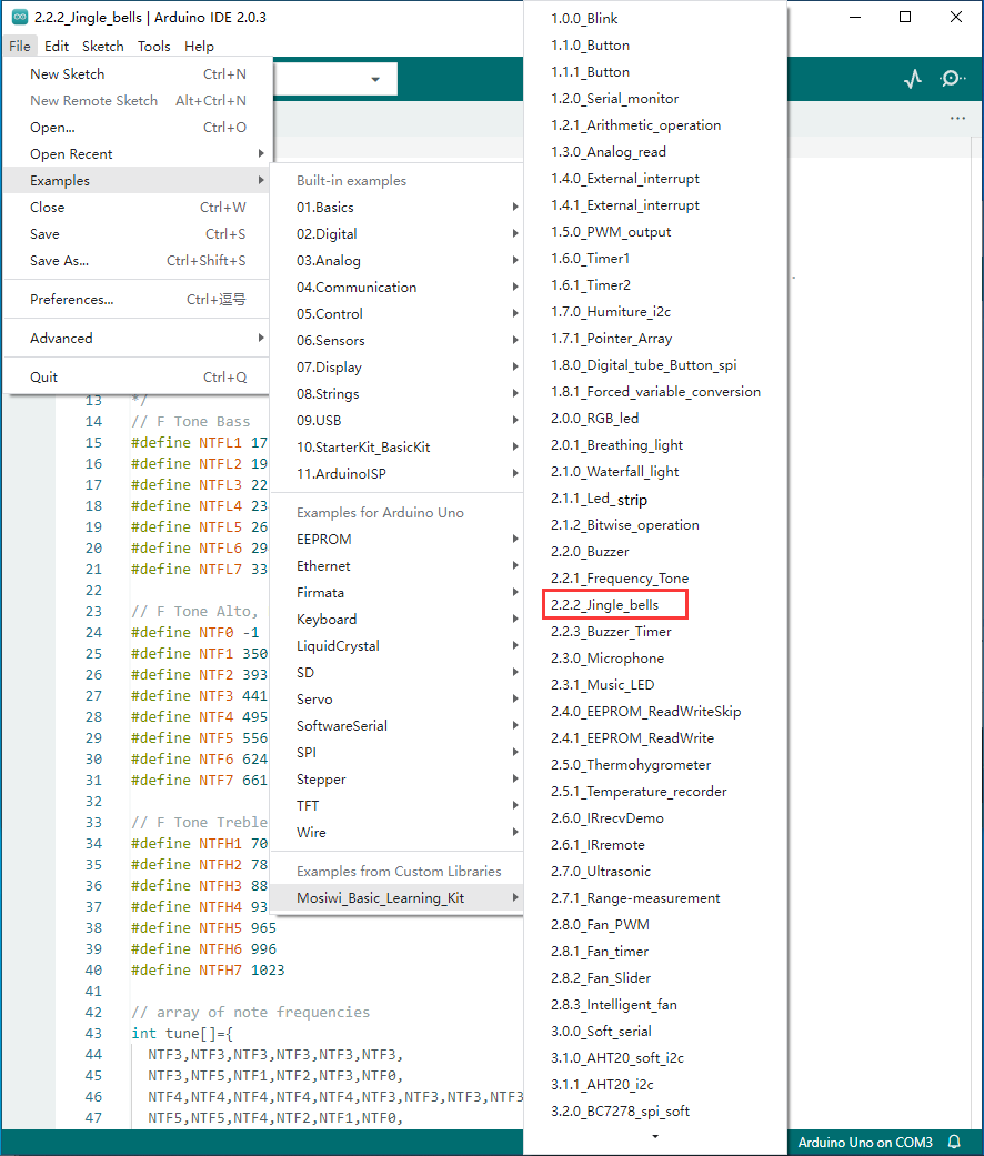
Select motherboard with COM port:

Upload code:

Experimental result:
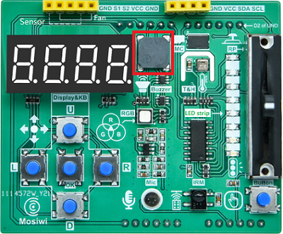
The buzzer on the expansion board will play the “Jingle_bells” song all the time.
End!
For more exciting tutorials, check out the basic tutorial!